Search

Types of Power Supply

There are many types of power supply. Most are designed to convert high voltage AC mains electricity to a suitable low voltage supply for electronics circuits and other devices. A power supply can by broken down into a series of blocks, each of which performs a particular function.

For example a 5V regulated supply:

Block Diagram of a Regulated Power Supply System

Each of the blocks is described in more detail below:

  • Transformer - steps down high voltage AC mains to low voltage AC.
  • Rectifier - converts AC to DC, but the DC output is varying.
  • Smoothing - smooths the DC from varying greatly to a small ripple.
  • Regulator - eliminates ripple by setting DC output to a fixed voltage.
Power supplies made from these blocks are described below with a circuit diagram and a graph of their output:

Jumaat, 8 Mac 2013

Save Electricity circuit

Do you know how to work his usual power saving devices in the market is shaped like a dry battery with a plug into an outlet?. Actually you can create your own tool with much better quality with much cheaper price.


Because of the way it works is to reduce the magnitude from cosine curve AC current that will be read on the gauge kilometer. Device work if there is air conditioning load passes through a coil of wire sensors to measure the AC current which is being passed.
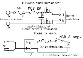
power saver circuit diagram
Power Saver Circuit

A very influential component in the AC circuit is a capacitor and inductor. Therefore we need to filter the AC current before it enters our home electricity network. Obviously we did not perform the act of theft of electricity, and this tool will not be detected by the device are as follows . How to installation, Here I would include a scheme of the circuit which will be installed close to the mile. The closer, the more optimal the way it works, use good quality capacitors, for security MCB here, serves to prevent the occurrence of shorting out due to damage to the capacitor. Then Enter in box or plastic box which is strong enough. Better capacitor in the cast by GIP's or cement, so that power is wasted heat well.

Tiada ulasan:

Catat Ulasan

Power Supplies

Power Supplies

Types of Power Supply

There are many types of power supply. Most are designed to convert high voltage AC mains electricity to a suitable low voltage supply for electronics circuits and other devices. A power supply can by broken down into a series of blocks, each of which performs a particular function.

For example a 5V regulated supply:

Block Diagram of a Regulated Power Supply System

Each of the blocks is described in more detail below:

  • Transformer - steps down high voltage AC mains to low voltage AC.
  • Rectifier - converts AC to DC, but the DC output is varying.
  • Smoothing - smooths the DC from varying greatly to a small ripple.
  • Regulator - eliminates ripple by setting DC output to a fixed voltage.
Power supplies made from these blocks are described below with a circuit diagram and a graph of their output:

Transformer + Rectifier


DC power supply, transformer + rectifier

The varying DC output is suitable for lamps, heaters and standard motors. It is not suitable for electronic circuits unless they include a smoothing capacitor.

Further information: Transformer | Rectifier

Dual Supplies


Dual power supplySome electronic circuits require a power supply with positive and negative outputs as well as zero volts (0V). This is called a 'dual supply' because it is like two ordinary supplies connected together as shown in the diagram.

Dual supplies have three outputs, for example a ±9V supply has +9V, 0V and -9V outputs.

Transformer + Rectifier + Smoothing


Smooth DC power supply, transformer + rectifier + smoothing

The smooth DC output has a small ripple. It is suitable for most electronic circuits.

Further information: Transformer | Rectifier | Smoothing

Transformer + Rectifier + Smoothing + Regulator


Regulated DC power supply, transformer + rectifier + smoothing + regulator

The regulated DC output is very smooth with no ripple. It is suitable for all electronic circuits.

Further information: Transformer | Rectifier | Smoothing | Regulator

Transformer


Transformers convert AC electricity from one voltage to another with little loss of power. Transformers work only with AC and this is one of the reasons why mains electricity is AC.

Step-up transformers increase voltage, step-down transformers reduce voltage. Most power supplies use a step-down transformer to reduce the dangerously high mains voltage (230V in UK) to a safer low voltage.

The input coil is called the primary and the output coil is called thesecondary. There is no electrical connection between the two coils, instead they are linked by an alternating magnetic field created in the soft-iron core of the transformer. The two lines in the middle of the circuit symbol represent the core.

Transformers waste very little power so the power out is (almost) equal to the power in. Note that as voltage is stepped down current is stepped up.

The ratio of the number of turns on each coil, called the turns ratio, determines the ratio of the voltages. A step-down transformer has a large number of turns on its primary (input) coil which is connected to the high voltage mains supply, and a small number of turns on its secondary (output) coil to give a low output voltage.

turns ratio = Vp = Np and power out = power in
VsNsVs × Is = Vp × Ip
Vp = primary (input) voltage
Np = number of turns on primary coil
Ip = primary (input) current
Vs = secondary (output) voltage
Ns = number of turns on secondary coil
Is = secondary (output) current

Rectifier


There is more information
about rectifiers on the
Electronics in Meccano
website.
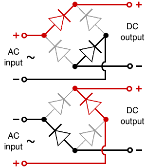
There are several ways of connecting diodes to make a rectifier to convert AC to DC. The bridge rectifier is the most important and it produces full-wave varying DC. A full-wave rectifier can also be made from just two diodes if a centre-tap transformer is used, but this method is rarely used now that diodes are cheaper. Asingle diode can be used as a rectifier but it only uses the positive (+) parts of the AC wave to produce half-wave varying DC.

Bridge rectifier

A bridge rectifier can be made using four individual diodes, but it is also available in special packages containing the four diodes required. It is called a full-wave rectifier because it uses all the AC wave (both positive and negative sections). 1.4V is used up in the bridge rectifier because each diode uses 0.7V when conducting and there are always two diodes conducting, as shown in the diagram below. Bridge rectifiers are rated by the maximum current they can pass and the maximum reverse voltage they can withstand (this must be at least three times the supply RMS voltage so the rectifier can withstand the peak voltages). Please see the Diodes page for more details, including pictures of bridge rectifiers.
Operation of a Bridge RectifierFull-wave Varying DC
Bridge rectifier
Alternate pairs of diodes conduct, changing over
the connections so the alternating directions of
AC are converted to the one direction of DC.
Output: full-wave varying DC
(using all the AC wave)

Single diode rectifier

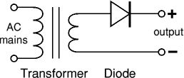
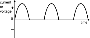
A single diode can be used as a rectifier but this produces half-wave varying DC which has gaps when the AC is negative. It is hard to smooth this sufficiently well to supply electronic circuits unless they require a very small current so the smoothing capacitor does not significantly discharge during the gaps. Please see the Diodes page for some examples of rectifier diodes.
Single diode rectifierHalf-wave Varying DC
Single diode rectifierOutput: half-wave varying DC
(using only half the AC wave)

Smoothing

Smoothing is performed by a large value electrolytic capacitor connected across the DC supply to act as a reservoir, supplying current to the output when the varying DC voltage from the rectifier is falling. The diagram shows the unsmoothed varying DC (dotted line) and the smoothed DC (solid line). The capacitor charges quickly near the peak of the varying DC, and then discharges as it supplies current to the output.


Smoothing

Note that smoothing significantly increases the average DC voltage to almost the peak value (1.4 × RMSvalue). For example 6V RMS AC is rectified to full wave DC of about 4.6V RMS (1.4V is lost in the bridge rectifier), with smoothing this increases to almost the peak value giving 1.4 × 4.6 = 6.4V smooth DC.

Smoothing is not perfect due to the capacitor voltage falling a little as it discharges, giving a small ripple voltage. For many circuits a ripple which is 10% of the supply voltage is satisfactory and the equation below gives the required value for the smoothing capacitor. A larger capacitor will give less ripple. The capacitor value must be doubled when smoothing half-wave DC.

There is more information
about smoothing on the
Electronics in Meccano
website.
Smoothing capacitor for 10% ripple, C =5 × Io
Vs × f
C = smoothing capacitance in farads (F)
Io = output current from the supply in amps (A)
Vs = supply voltage in volts (V), this is the peak value of the unsmoothed DC
f = frequency of the AC supply in hertz (Hz), 50Hz in the UK


Regulator


Voltage regulatorVoltage regulator, photograph © Rapid Electronics
Voltage regulator
Photograph © Rapid Electronics

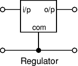
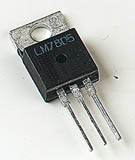
Voltage regulator ICs are available with fixed (typically 5, 12 and 15V) or variable output voltages. They are also rated by the maximum current they can pass. Negative voltage regulators are available, mainly for use in dual supplies. Most regulators include some automatic protection from excessive current ('overload protection') and overheating ('thermal protection').

Many of the fixed voltage regulator ICs have 3 leads and look like power transistors, such as the 7805 +5V 1A regulator shown on the right. They include a hole for attaching a heatsink if necessary.

Please see the Electronics in Meccano website for more information about voltage regulator ICs.

Zener diode
zener diode
a = anode, k = cathode
Zener diode circuit

Zener diode regulator

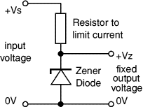
For low current power supplies a simple voltage regulator can be made with a resistor and a zener diode connected in reverse as shown in the diagram. Zener diodes are rated by their breakdown voltage Vz andmaximum power Pz (typically 400mW or 1.3W).

The resistor limits the current (like an LED resistor). The current through the resistor is constant, so when there is no output current all the current flows through the zener diode and its power rating Pz must be large enough to withstand this.

Please see the Diodes page for more information about zener diodes.

Choosing a zener diode and resistor:

  1. The zener voltage Vz is the output voltage required
  2. The input voltage Vs must be a few volts greater than Vz
    (this is to allow for small fluctuations in Vs due to ripple)
  3. The maximum current Imax is the output current required plus 10%
  4. The zener power Pz is determined by the maximum current: Pz > Vz × Imax
  5. The resistor resistance: R = (Vs - Vz) / Imax
  6. The resistor power rating: P > (Vs - Vz) × Imax
Example: output voltage required is 5V, output current required is 60mA.
There is more information
about regulators on the
Electronics in Meccano
website.
  1. Vz = 4.7V (nearest value available)
  2. Vs = 8V (it must be a few volts greater than Vz)
  3. Imax = 66mA (output current plus 10%)
  4. Pz > 4.7V × 66mA = 310mW, choose Pz = 400mW
  5. R = (8V - 4.7V) / 66mA = 0.05kohm = 50ohm, choose R = 47ohm
  6. Resistor power rating P > (8V - 4.7V) × 66mA = 218mW, choose P = 0.5W