Types of Power Supply
There are many types of power supply. Most are designed to convert high voltage AC mains electricity to a suitable low voltage supply for electronics circuits and other devices. A power supply can by broken down into a series of blocks, each of which performs a particular function.
For example a 5V regulated supply:
Each of the blocks is described in more detail below:
- Transformer - steps down high voltage AC mains to low voltage AC.
- Rectifier - converts AC to DC, but the DC output is varying.
- Smoothing - smooths the DC from varying greatly to a small ripple.
- Regulator - eliminates ripple by setting DC output to a fixed voltage.
Jumaat, 8 Mac 2013
Standard Power Supply
 |
| Note that the supply shown is for a mono amplifier; a stereo outfit needs two supplies. |
6VDC to 12VDC Power Supply Inverter

Part List:
R1, R4 2.2K 1/4W Resistor
R2, R3 4.7K 1/4W Resistor
R5 1K 1/4W Resistor
R6 1.5K 1/4W Resistor
R7 33K 1/4W Resistor
R8 10K 1/4W Resistor
C1,C2 0.1uF Ceramic Disc Capacitor
C3 470uF 25V Electrolytic Capcitor
D1 1N914 Diode
D2 1N4004 Diode
D3 12V 400mW Zener Diode
Q1, Q2, Q4 BC547 NPN Transistor
Q3 BD679 NPN Transistor
L1 See Notes
MISC Heatsink For Q3, Binding Posts (For Input/Output), Wire, Board
Power Supply adjustable 1.3V - 12.2V 1A
In addition, the power supply circuit is also equipped with over-current protection or shield against belebih flow. Power supply circuit is very simple, but the quality is quite good, made her basiskan regulator IC LM723 is a pretty legendary.

Description:
R2 to set the output voltage. The maximum current is determined by R3, over-current protection circuit inside the LM723 to detect the voltage on R3, if it reaches 0.65 V, the voltage output will be off her. So the current through R3 can not exceed 0.65 / R3 although output short-circuit in his.
C3 and C4 are ceramic capacitors, as much as possible directly soldered to the PCB, this is because the LM723 is prone to oscillation that is not cool.
LM723 works with 9.5V input voltage to 40 V DC and the LM723 can generate its own current of 150mA when the output voltage is not more than 6-7V under input voltage.
Specifications:
Output (value estimated):
Vmin = (R4 + R5) / (R5 * 1.3)
Vmax = (7.15 / R5) * (R4 + R5)
Imax = 0.65/R3
Max. Power on R3: 0.42/R3
Min. DC Input Voltage (pin 12 to pin 7): Vmax + 5
Component List:
B1 40V/2.5A
C1 2200uF (3300uF even better)
C2 4.7uF
C3 100nF
C4 1NF
C5 330nF
C6 100uF
Green LED D1
D2 1N4003
F1 0.2A F
F2 2A M
IC1 LM723 (in a DIL14 plastic package)
R1 1k
R2 Pot. 5k
R3 0.56R/2W
R4 3.3k
R5 4.7k
S1 250V/1A
T1 2N3055 on a heatsink 5K / W
TR1 220V/17V/1.5
5V output Switching Power Supply
You can make the stable voltage by using the 3 terminal regulator like LM317. However, because the output electric current and the inputted electric current are the same approximately, the difference between the input electric power (The input voltage x The input electric current) and the output power (The output voltage x The output current) is consumed as the heat with the regulator. Because it is, the efficiency isnot good.

Save Electricity circuit
Because of the way it works is to reduce the magnitude from cosine curve AC current that will be read on the gauge kilometer. Device work if there is air conditioning load passes through a coil of wire sensors to measure the AC current which is being passed.
 |
| Power Saver Circuit |
Power Supply no transformer using IC and MOSFET
- nsurance
- Debt Consolidation
- Term life insurance

 |
| Schematics MOSFET use BUZ74 and IC CA3130E |
Simple Power Supply Transformerless

This circuit has a voltage output of about 12 volts with 20mA current voltage. And this series of works using capacitive reactance and resistance are not using, this will reduce the heat on the circuit.
To be safe when there is a short-circuit series, always use a fuse on the input voltage is 220V. Here is a series of power supply without a simple transfomer.
Part List
R1 - 1.8K 1W
R2 - 100Ω
C1 - 0.47µF 400V
C2 - 1000µF 50V
D1 - 1N4007
D2 - 1N4007
D3 - 1N4007
D4 - 1N4007
ZD1 - 16V Zener Diode
ZD2 - 16V Zener Diode
ZD3 - 12V Zener Diode
Types of Power Supply
There are many types of power supply. Most are designed to convert high voltage AC mains electricity to a suitable low voltage supply for electronics circuits and other devices. A power supply can by broken down into a series of blocks, each of which performs a particular function.
For example a 5V regulated supply:
Each of the blocks is described in more detail below:
- Transformer - steps down high voltage AC mains to low voltage AC.
- Rectifier - converts AC to DC, but the DC output is varying.
- Smoothing - smooths the DC from varying greatly to a small ripple.
- Regulator - eliminates ripple by setting DC output to a fixed voltage.
Transformer + Rectifier
The varying DC output is suitable for lamps, heaters and standard motors. It is not suitable for electronic circuits unless they include a smoothing capacitor.
Further information: Transformer | Rectifier
Dual Supplies
 Some electronic circuits require a power supply with positive and negative outputs as well as zero volts (0V). This is called a 'dual supply' because it is like two ordinary supplies connected together as shown in the diagram.
Dual supplies have three outputs, for example a ±9V supply has +9V, 0V and -9V outputs.
Transformer + Rectifier + Smoothing
The smooth DC output has a small ripple. It is suitable for most electronic circuits.
Further information: Transformer | Rectifier | Smoothing
Transformer + Rectifier + Smoothing + Regulator
The regulated DC output is very smooth with no ripple. It is suitable for all electronic circuits.
Further information: Transformer | Rectifier | Smoothing | Regulator
Rectifier
| There is more information about rectifiers on the Electronics in Meccano website. |
Bridge rectifier
A bridge rectifier can be made using four individual diodes, but it is also available in special packages containing the four diodes required. It is called a full-wave rectifier because it uses all the AC wave (both positive and negative sections). 1.4V is used up in the bridge rectifier because each diode uses 0.7V when conducting and there are always two diodes conducting, as shown in the diagram below. Bridge rectifiers are rated by the maximum current they can pass and the maximum reverse voltage they can withstand (this must be at least three times the supply RMS voltage so the rectifier can withstand the peak voltages). Please see the Diodes page for more details, including pictures of bridge rectifiers. |  |
| Bridge rectifier Alternate pairs of diodes conduct, changing over the connections so the alternating directions of AC are converted to the one direction of DC. | Output: full-wave varying DC (using all the AC wave) |
Single diode rectifier
A single diode can be used as a rectifier but this produces half-wave varying DC which has gaps when the AC is negative. It is hard to smooth this sufficiently well to supply electronic circuits unless they require a very small current so the smoothing capacitor does not significantly discharge during the gaps. Please see the Diodes page for some examples of rectifier diodes. |  |
| Single diode rectifier | Output: half-wave varying DC (using only half the AC wave) |
Smoothing
Smoothing is performed by a large value electrolytic capacitor connected across the DC supply to act as a reservoir, supplying current to the output when the varying DC voltage from the rectifier is falling. The diagram shows the unsmoothed varying DC (dotted line) and the smoothed DC (solid line). The capacitor charges quickly near the peak of the varying DC, and then discharges as it supplies current to the output.
Note that smoothing significantly increases the average DC voltage to almost the peak value (1.4 × RMSvalue). For example 6V RMS AC is rectified to full wave DC of about 4.6V RMS (1.4V is lost in the bridge rectifier), with smoothing this increases to almost the peak value giving 1.4 × 4.6 = 6.4V smooth DC.
Smoothing is not perfect due to the capacitor voltage falling a little as it discharges, giving a small ripple voltage. For many circuits a ripple which is 10% of the supply voltage is satisfactory and the equation below gives the required value for the smoothing capacitor. A larger capacitor will give less ripple. The capacitor value must be doubled when smoothing half-wave DC.
| There is more information about smoothing on the Electronics in Meccano website. |
| Smoothing capacitor for 10% ripple, C = | 5 × Io |
| Vs × f |
Io = output current from the supply in amps (A)
Vs = supply voltage in volts (V), this is the peak value of the unsmoothed DC
f = frequency of the AC supply in hertz (Hz), 50Hz in the UK
Regulator
 | 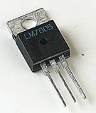 |
| Voltage regulator Photograph © Rapid Electronics
|
Many of the fixed voltage regulator ICs have 3 leads and look like power transistors, such as the 7805 +5V 1A regulator shown on the right. They include a hole for attaching a heatsink if necessary.
Please see the Electronics in Meccano website for more information about voltage regulator ICs.
| zener diode a = anode, k = cathode |
 |
Zener diode regulator
For low current power supplies a simple voltage regulator can be made with a resistor and a zener diode connected in reverse as shown in the diagram. Zener diodes are rated by their breakdown voltage Vz andmaximum power Pz (typically 400mW or 1.3W).The resistor limits the current (like an LED resistor). The current through the resistor is constant, so when there is no output current all the current flows through the zener diode and its power rating Pz must be large enough to withstand this.
Please see the Diodes page for more information about zener diodes.
Choosing a zener diode and resistor:
- The zener voltage Vz is the output voltage required
- The input voltage Vs must be a few volts greater than Vz
(this is to allow for small fluctuations in Vs due to ripple) - The maximum current Imax is the output current required plus 10%
- The zener power Pz is determined by the maximum current: Pz > Vz × Imax
- The resistor resistance: R = (Vs - Vz) / Imax
- The resistor power rating: P > (Vs - Vz) × Imax
| There is more information about regulators on the Electronics in Meccano website. |
- Vz = 4.7V (nearest value available)
- Vs = 8V (it must be a few volts greater than Vz)
- Imax = 66mA (output current plus 10%)
- Pz > 4.7V × 66mA = 310mW, choose Pz = 400mW
- R = (8V - 4.7V) / 66mA = 0.05k
 = 50, choose R = 47
 - Resistor power rating P > (8V - 4.7V) × 66mA = 218mW, choose P = 0.5W